jedihobbit
Rated XXX

|
 Posted: Tue, 15 Apr 2008 21:14:58 Post Subject: BluHaz First mATX Build Posted: Tue, 15 Apr 2008 21:14:58 Post Subject: BluHaz First mATX Build |
 |
|
While my first work logs here are for DreamCatcher, DreamCatcher v2.0, and Yodaâs SMN they are not my first attempt at a mATX case. BluHaz was the first, with a Rev.2, which became BluHaz reDux, and is finishing out as BluHaz reDux v2.0.
In the Beginning
The idea of a mATX acrylic case came about around the end of â03 / beginning of â04 when I bought the case at amdmb (now pcper) in the F/S section. The first set of specs were: Chaintech 7NIL1, 2500+ TâBred, Tyan 9700 PRO, 2 x 256 PC3200, 350W PSU, CD-RW, 1.44, & a 40Gig HDD. This was to be my âsuper bling-blingâ folder. Needless to say life and âengineering issuesâ got in the way and it wasnât âcompletedâ until October/November â05.
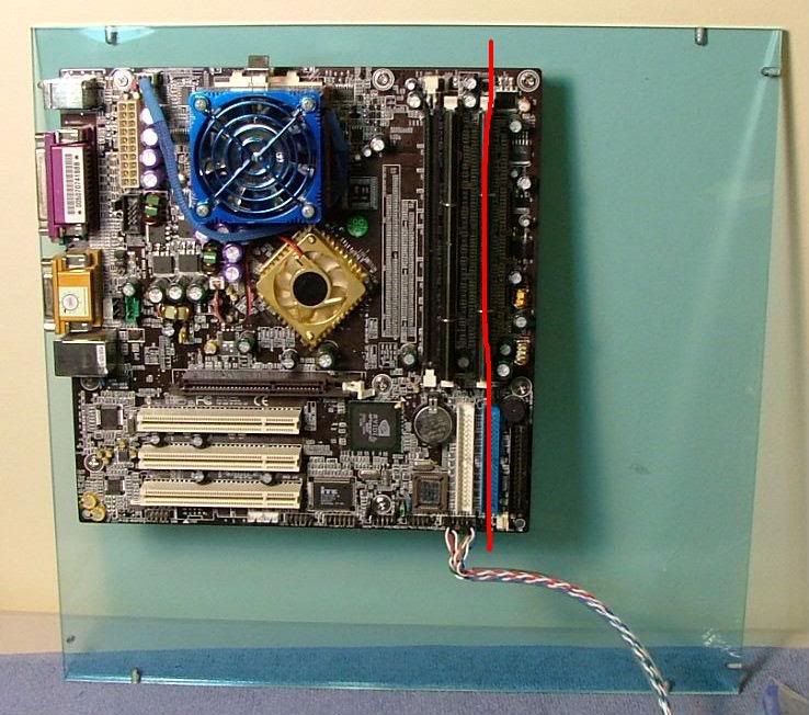
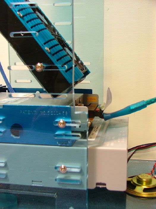
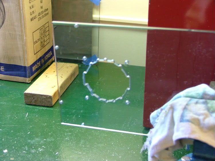
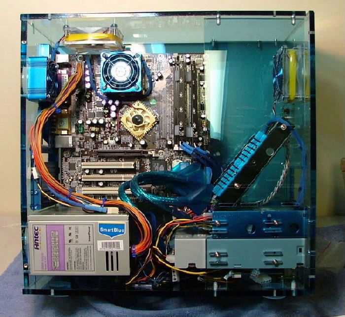
First thing I realized is there are 2 sizes of mATX boards >> case = âoriginalâ size & 7NIL1 = âlargerâ!! The extra dim slot did me in. First the mobo extended beyond the drive side plate & the side panel/mobo tray didnât provide for the extra mounting holes. Second the HDD and cables covered a lot of stuff!! Mobo pic with the red line shows approximately how much it covered the drive side plate. The pic with the rectangle shows about where the HDD sits. The pic with the circles shows where I added 2 standoffs (should have been three).
  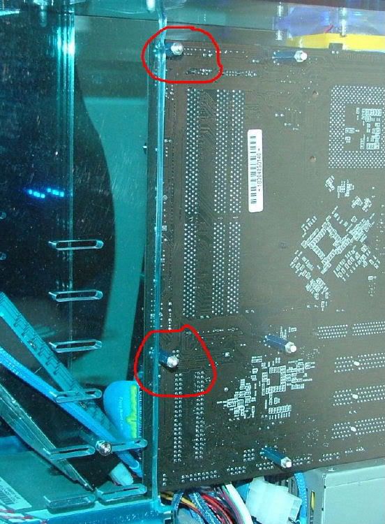
The hardware package came with mounting âextensionsâ for drive mounting in the cage. As shown above, I drill and tapped the acrylic side panel. This gave me the support for the mobo I needed, but now they hit the drive cage. So I attempted to drill two clearance holes for the stand offs in the one dive cage side. Lesson learned >> acrylic can be very brittle! I ended up having to make a long ânotchâ to allow for the added posts to slide in. That required using a hack saw, then file, 250, 400, 600, & finally 1000 grit to get a âfinishedâ look.
As noted above the HDDâs âstockâ location wouldnât work because it covered minor things like the floppy connector, cmos jumper, etc. So dropped the floppy down in a bay adapter and âfitâ the HDD wherever I could. Using a rat-tail file I modified the mounting slots in the drive cage. Also had to mount it âup side downâ because of the cables.
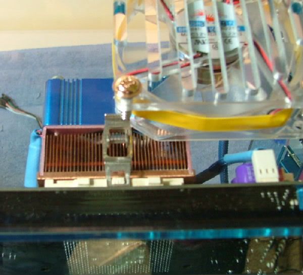
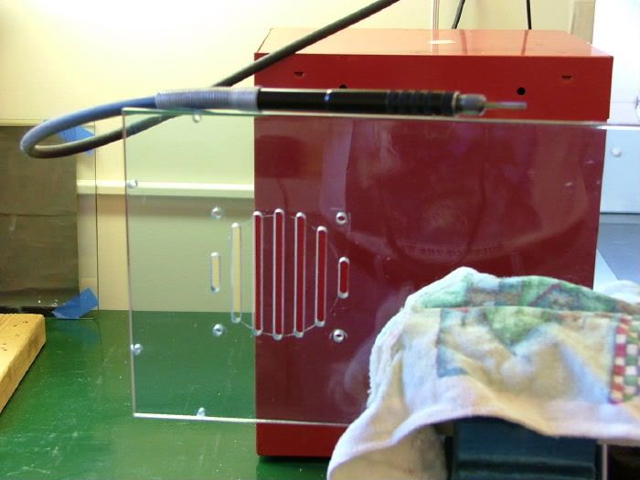
Because of not using a âstockâ amd hsf, the blowhole fan needed to be notched to allow it to fit. After the initial assembly, it was determined the original machined grill blocked half of the exiting air, so that was cut out. You can see how much blockage there is in the pic showing the notched fan. The next few pictures show scribing the cutout using the fan grill and the âfinishedâ cut out.
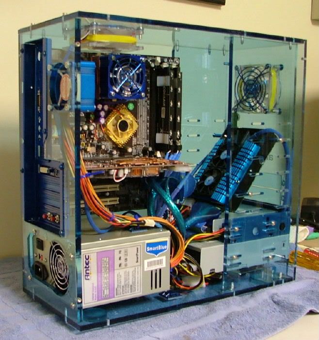
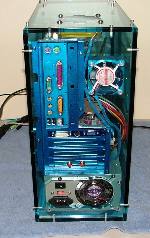
Bling- bling issues were covered by 1.) painting the I/O plate, PCI cover plates and frame, gpu end plate, fan grills, and the aluminum housings on the two AOC 60mm fans 2) two 80mm blue led fans 3) memory "running" led light mod. Modified a pci plate on this so both switches are together. These are the two red momentary switches seen in the back view 4) painting the floppy faceplate and adapter frame. The original CD-RWâs faceplate was painted but the drive was too deep for the case, and got "lazy" with the new drive.
Future plans: 1) Paint the combo drive faceplate? 2) Install a 3.5 bay fan controller for the 80mms and the one 60mm, 3) Sleeve the PSU and put on a blue acrylic cover, 4) Consider reworking the PSU mounting area to allow turning the PSU over, 5) Eliminating the floppy and replace with a multiple card reader/multi-function panel?
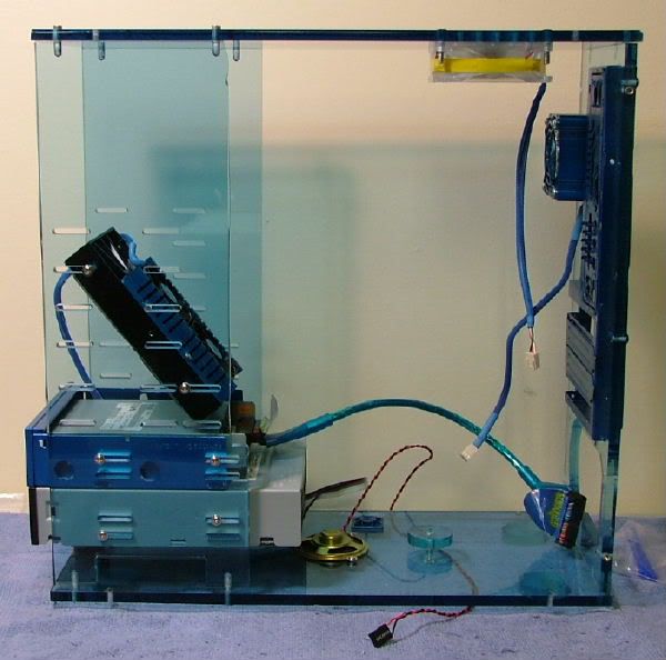
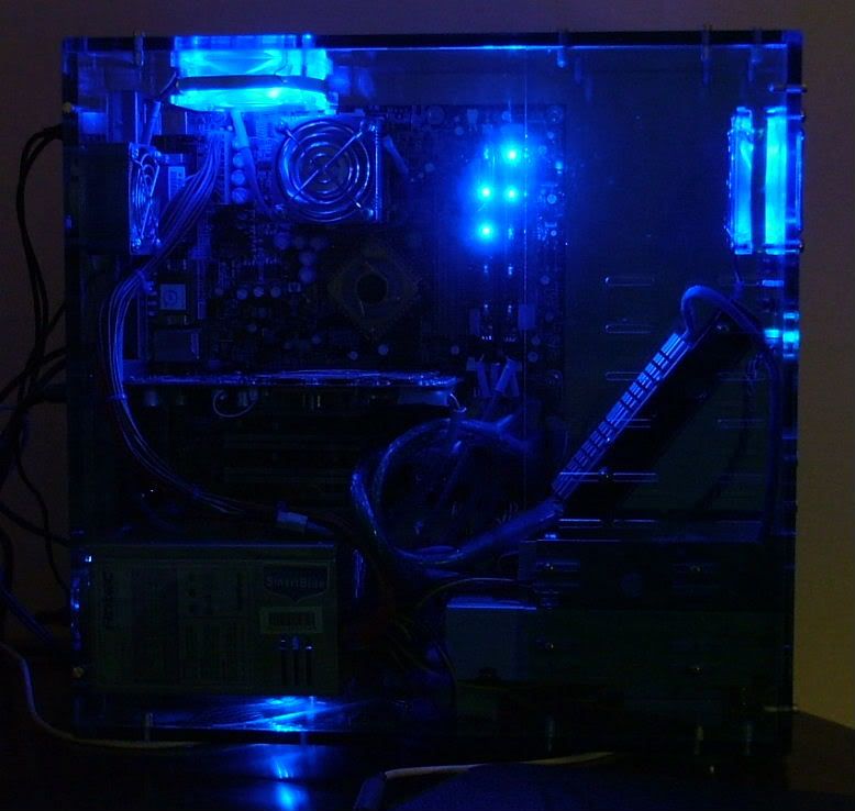
Also if & when I redo the PSU (#3 above) think I'll try to "bob" off some of the cabling as it is real tight (see the interior side view).
Since the âfunâ has started to wane with the desire just to have the system running, if the floppy is removed all of the components will be black to avoid having to paint anymore. (Getting "lazy")
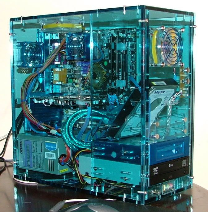
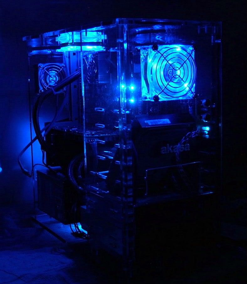
Here are some of the âfinishedâ pictures:
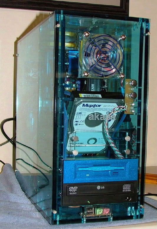  
Here is the rear view, which shows the memory led mod switches. When I try swapping out the current 60mm fan for a led one, I need to find longer screws so to add an exterior fan grill.
Also this shot was taken before the blow hole was reworked.
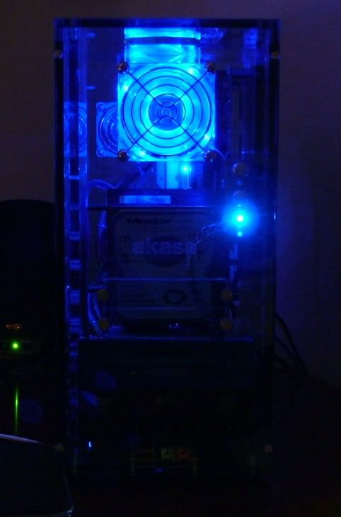
Here it is in the dark
   |
|