External Features (continued):
The image below provides a look at one of the four feet found on the bottom of the case. They swing out for greater stability, and click into place at a few positions, which could prove handy if some installations didn't have enough room for them to be fully extended.
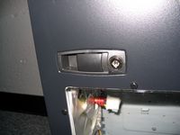
The image below is provided to show detail on the locking latch found on the side panel. Once unlocked, simply depress the latches, and pull the panel away from the case. Most cases just have one latch, making removal a one handed operation, so those in a rush may not appreciate having to use both hands to get the side open.
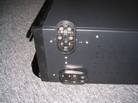
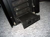
The images below provide a look at some of the front bays. The very top bay includes the power button, reset switch, power LED, and hard drive activity LED. It is removable, and can be relocated to any bay that the user may choose. The small perforated insert is also removable, and a 3.5" drive can be mounted in its place. The very bottom bay features a drawer for storing small parts. This bay is also removable, and could be eliminated if a user found they really need all eleven bays.
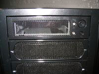 
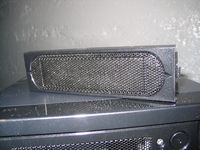
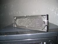
The bulk of the bay covers are the same plastic frame with a perforated mesh insert that allows air to flow into the case. A sample bay cover is shown below, and it can be seen that the center portion of the perforation can be removed for a 3.5" device, although there are only mounts provided for such a device behind one of them. The back of each bay cover features an filter of sorts to help keep all the air entering the case clean free of dust. The filter is removable, and could probably just be rinsed off, dried out, and slapped back on for continued use. Cleaning all of them may be a nuisance, since there are so many, but I'll report back on that in a few months.
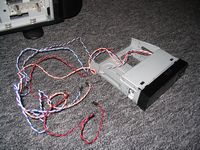
The below left image shows the top bay insert removed, and all the wires connected to the backside of it. As mentioned, the power button, reset switch, power LED, and HDD activity LED are featured here, and each is provided with an ample lead to reach your motherboard's header from any possible location. The below right image shows the contents of a small cardboard box included inside the case. As pictured, we have another 90mm fan, a fan mounting bracket, a bag of mounting hardware, sleeves to use in the water cooling punch outs on the back of the case, and a few clear tabs which I didn't know what to do with.
 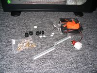
The spare 90mm fan is meant to be mounted just below the perforated opening on the top of the case. So, if the two exhaust fans, and the natural rising of the heat weren't cutting it, this fan can be installed for an added boost to the system's cooling. The mounting bracket will attach to the frame just behind the power supply, and the manual provides much needed details on this process.
Please read on to the next page for more... Next
Page 1 | Page 2 | Page 3 | Page 4 | Page 5 | Page 6 | Home | Forum | Review Index
|
|


